
Introduction
What is Splicing?
Palette combines different materials and feeds them into 3D printers to create objects with multiple colors and materials. Heat, compression, and cooling is used to join these filaments together.
Filament Tips
For best results it is recommended to:
- Use filament that is within +/- 0.03 mm spec of 1.75 mm to create the best quality splices.
- Avoid using brittle filament. Check that the filament is not brittle before splicing or printing. If the filament snaps easily without much effort, it's likely become too brittle.
- Use filament storage to keep spools dry.
How to tell if a splice and your splice tuning settings will create a strong splice:
- The splice will remain intact when feeding into the extruder. The splice is pliable and takes multiple bends to break.
- The splice has a diameter of approximately 1.75 mm ± 0.10 mm. If possible, it is best to measure the diameter with digital calipers, with the filament placed vertically so the splice is measured at multiple points.
How to Splice Tune
- Test splice settings using the Splice Tuning menu on Palette. Evaluate the splice for its strength by bending it or measuring with digital calipers (steps 1-2). If splicing two materials of different rigidity, also test the reverse splice order (step 3)
- Save splice settings in Canvas, and select material profiles (steps 4-6)
Glossary
Splice - The fusion of two different filaments. This can refer to the connection of the two filaments, or a length of filament where two filaments have joined together
Splicing - The operation on Palette of fusing two different filaments together
Splice core - The assembled component on Palette where splices are created
Splice tube - A piece of PTFE tubing that is inserted into the splice core, used to contain and guide the filament during splicing
Heat - The amount of time heat is applied during a splice
Compression - The distance that the two filament pieces are pressed into each other
Cooling - The amount of time the splice has to cool down after exiting the splice core
Splice tuning - The menu option and operation on Palette that allows you to test heat, compression and cooling factors applied to the selected filament
Splice settings, splice factors or splice tuning values - The set of heat, compression, and cooling factors applied to create a splice (e.g. 0,0,0 or 2,0,2)
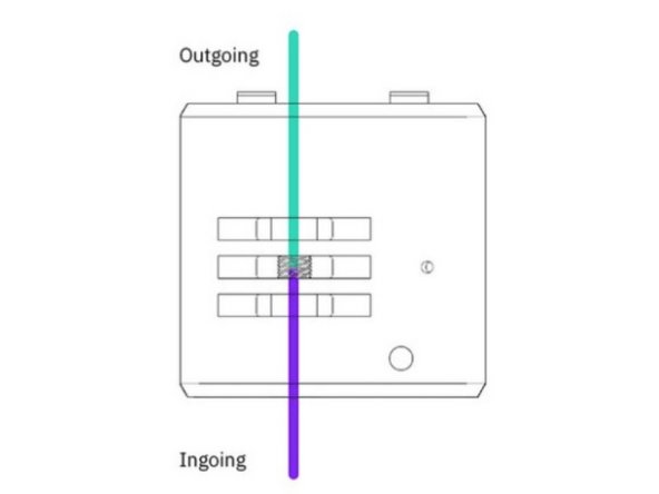
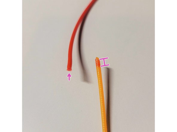
Outgoing filament - The first length of filament which is preheated in the splice core. It will also be seen first exiting the output on Palette (see step 3)
Ingoing filament - The second length of filament which meets the preheated outgoing filament in the splice. This piece of filament will exit the output on Palette after the outgoing piece (see step 3)
Drives - Inputs on Palette where filament is inserted. The number of inputs also corresponds to the colors available in the Projects Toolbox in Canvas (see step 6)
-
-
From Palette's main screen tap Controls > Splice Tuning.
-
Clear the unit of any filament before starting, and then insert the outgoing tube.
-
You may use the small outgoing tube when doing splice tuning so the filament will be guided out of the unit.
-
-
-
Heat - Each increment of 1 adds an additional 0.5 seconds to the heating time.
-
Substantially higher heating times may require more cooling time as well. These increases together may require slower print speeds so it is best not to heat more than is necessary.
-
Compress - Each increment of 1 adds additional compression of 0.5 mm to the splice.
-
Slight compression can be added to begin (+1, or +2), but a combination of excessive heat and compression can cause a bulging splice.
-
Cool - Each increment of 1 adds an additional one second to the cooling time.
-
Substantially higher cooling times may require slower print speeds.
-
Enter the desired settings, and then create the splice. Once the splice is complete, remove the outgoing tube by pushing down on the grommet, and from there the splice can be pulled out to be examined. The following splice tuning values for PLA can be used as a starting point if the default settings of 0,0,0 result in a weak splice: [1,1,1], [2,0,2].
-
Please see steps 7 and 8 for troubleshooting common splice issues and how to adjust heat, compression and cooling.
-
-
-
For some material combinations, the order with which you splice will affect the splicing parameters. When splicing in the reverse direction, it's possible that another set of splice tuning factors are used.
-
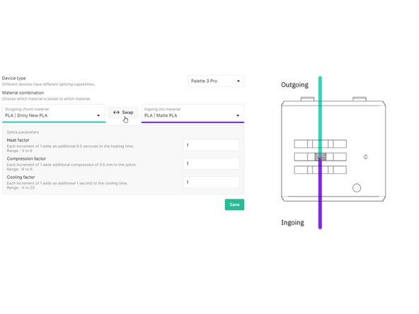
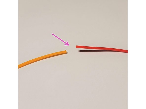
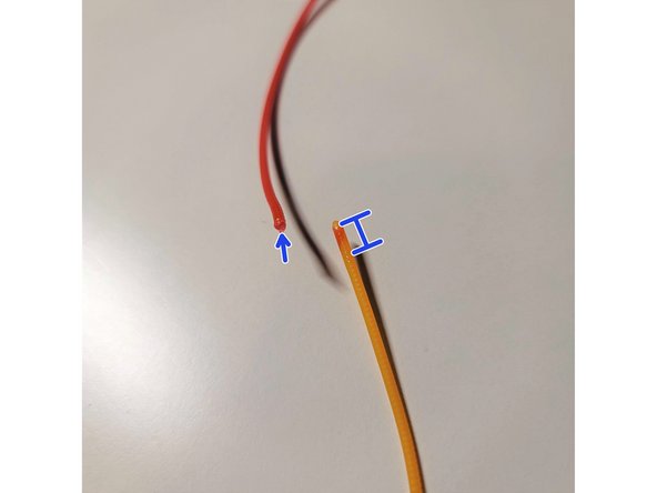
Outgoing filament is the first piece to be driven through the unit and the first color seen from the output. Ingoing filament is the second piece driven into the unit, and the last color seen leaving the output.
-
During splice tuning, Palette will splice the filament in drive 2 (ingoing) to the end of the filament in drive 1 (outgoing). The outgoing filament is heated first in the splice core before the ingoing is driven to meet it.
-
It is especially important to try splicing with both combinations when using two different materials. After testing the materials, swap the filaments between the two drives and try splice tuning again.
-
Material profiles in Canvas will allow you to enter the splice tuning for both directions when more than one material profile is selected in splice settings. See step 5.
-
-
-
From the Canvas main menu, go to Materials.
-
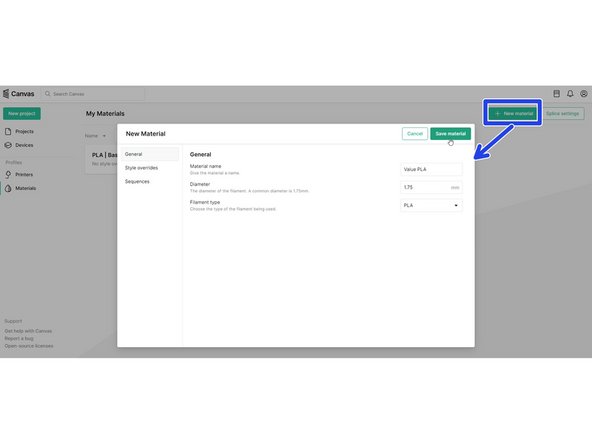
If you would like to create a new material profile, click the Add New Material button. You may edit the name of the material and the material type, and then Save material.
-
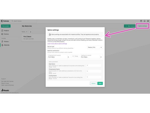
If you already have a material profile created, it can be selected and then click Splice Settings.
-
Check that the correct Palette model is selected for splice tuning
-
-
-
New materials can be created and splice tuning settings for each material can also be saved while working in a project.
-
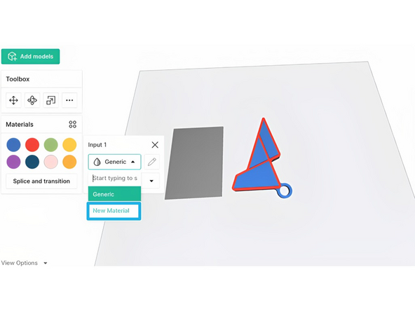
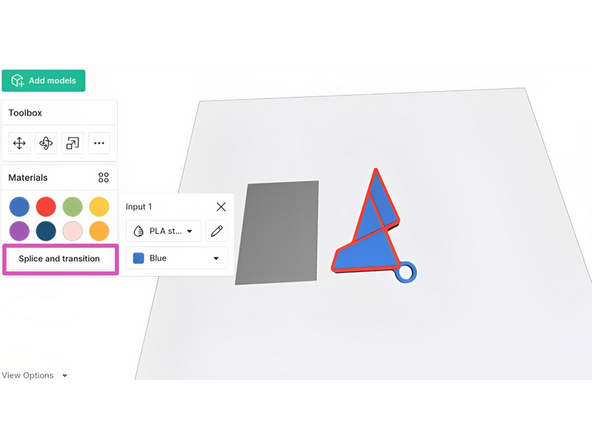
From the materials dropdown, select New material to create a new material profile
-
With a material profile selected for the input, selecting "Splice and transition" will open splice tuning settings.
-
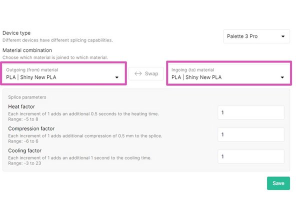
Check that the correct Palette model is selected for splice tuning.
-
-
-
Splicing same material: If the ingoing and outgoing materials are the same (ex. PLA - PLA), the splice parameters will also be the same regardless of which material is loaded into Palette first.
-
Only one set of values will be needed, and the option to reverse the ingoing and outgoing material will be disabled.
-
This would be used for different filament colors of the same manufacturer or material type. Only one material profile with custom splice tuning is needed.
-
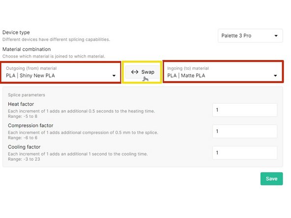
Splicing different materials: If the materials are different (ex. PLA - PETG, or two different brands of PLA that need tuning), the splice parameters may be different depending on the material being pushed (ingoing) and the material already in the splice core (outgoing).
-
Two sets of splice tuning values are possible with the ability to reverse the direction of the splice.
-
This would be used when the intended materials used for the print are of different filament types or from different manufacturers, where the splice tuning is required to strengthen the bond between the different materials.
-
The ‘outgoing’ filament is being heated at a standstill while the ‘ingoing’ filament is being pushed into the molten filament, compressed, and cooled to create a splice.
-
Once your splice tuning values are set, select Save to have these settings applied to your material profiles when they are used in a project (more on this in the next step).
-
-
-
Go to Projects to either start a new project or open an existing project. The toolbox on the left has color swatches that correspond to an input drive on Palette 3 (Pro).
-
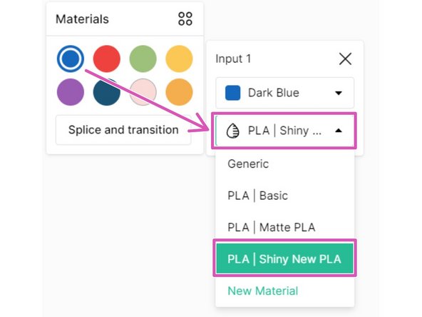
Printing with the same material: When returning to the project, on the toolbox click on a color swatch to check that the desired material profile is selected for each drive.
-
In this example, drives 1 (blue) and 2 (red) are of the same material but different colors will be loaded into Palette. If any remaining drives are used for this print, please ensure the material profile is also selected.
-
Drives 1 and 2 will use the one set of splice tuning values saved for the Shiny New PLA profile saved in the last step.
-
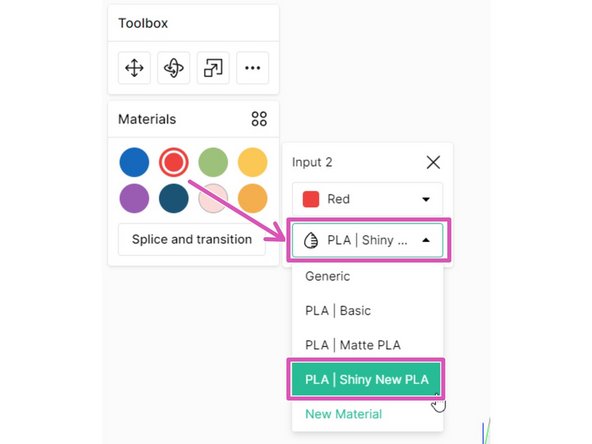
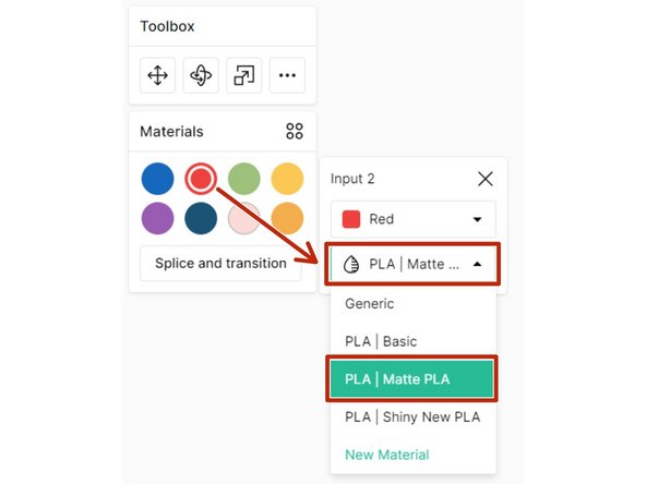
Printing with different materials: Click on a color swatch to select the desired material profile for each drive.
-
In this example, drive 1 (blue) is still using the Shiny New PLA profile like above, but drive 2 (red) will be using the Matte PLA profile. Select the intended material profile to be used for any remaining drives.
-
Because we have two different material profiles selected for drives 1 and 2, any splices between these two drives will use the two sets of splice tuning values saved between Shiny New PLA and Matte PLA in the last step. This includes the default order, and the reverse material order.
-
-
-
Brittle splices - This occurs when the filament is weak at the point of the splice. When applying a small amount of pressure, the splice snaps or breaks apart. A strong splice is malleable and can bend and act as if it were a single strand of filament without issue.
-
Increase the heat factor by one unit at a time testing the splice after each increase. For every increase of 1 heat you should also increase cooling by 1 increment to counteract this.
-
In this photo example, the brittle splice was created using very low heat and cooling in the negative values.
-
Necking splices - This occurs when splices are heated for too long, causing splices to ‘neck’ and create a thin string-like center at the splice. Decrease the heat factor and increase the cooling factor. You can also increase compression in small increments - too much compression will result in bulging and inconsistencies.
-
In this photo example, the necking splice was created using high heat and negative cooling.
-
Bulging splices - Bulging splices are most commonly caused by over-compression, and/or too little heat applied to the splice. Reduce compression first, and then try increasing the heat and cooling factors.
-
In this photo example, there is a bulge created by using more compression and no cooling. The bulging area is visibly wider than the rest of the filament strand.
-
If weak splices are occurring randomly, please see points 2 and 3 of 'Intermittent bad splice.'
-
-
-
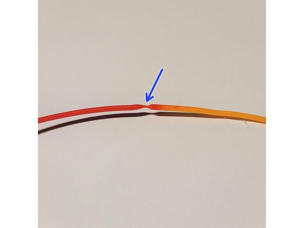
The compression factor adjusts the distance the two filament ends are compressed into each other. If the filaments are compressed too much or too little, it can negatively affect splice quality.
-
If the Compression Factor is set too low, you will see a small penetration cone in the splice.
-
In this photo example, the outgoing end (red) will have a shallower plunge, and there will be less of the residual outgoing red filament on the cone (orange).
-
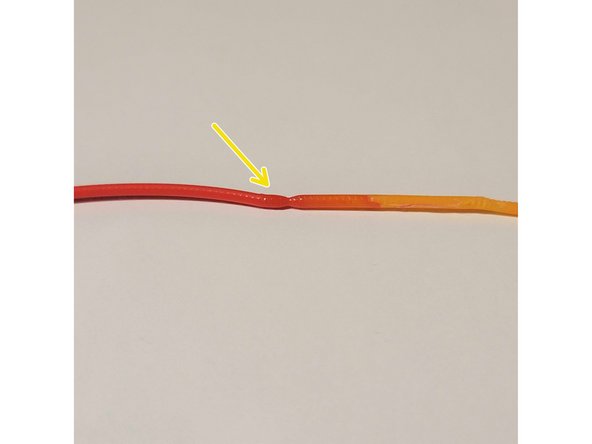
Increasing the compression factor to create a larger penetration cone, will help with splice quality.
-
In this photo example, the outgoing end (red) will have a deeper plunge, and there will be more of the residual outgoing red filament on the cone (orange).
-
Having too much compression can affect splice quality negatively as well, as Palette 3 will try to force the compression of the filament together. There may be skipping sound from the motors if the compression value is too high. Skipping will weaken the bond between the two filaments as it will cause the filaments to separate.
-
If you hear Palette 3’s ingoing drives skipping or grinding away at filament when splicing, decrease the compression factor incrementally by 1.
-


Splice Tuning Values
We have provided a chart with baseline values for different materials. This is intended to act as a starting point for splice tuning.
Behaviors During Printing
A broken or brittle splice often results with the printer continuing without any filament, a behavior known as air printing. You may still see some filament in the Palette unit or outgoing tube, but upon removing the outgoing tube from the printer's extruder there is no filament leading to the hot end.
An extremely large (bulging) splice may get caught in the splice core or in the extruder. If a bulging splice gets caught in the extruder or takes longer to pass through, you may notice slightly lower pings, since less filament is being extruded.
When a broken splice or jam occurs, you may see error 131 or 134 on Palette's screen.
--
If you have any additional questions, please send us a message at support@mosaicmfg.com.
Cancel: I did not complete this guide.
31 other people completed this guide.
