
Introduction
In this guide you will learn how to replace the cutter wheel assembly on Palette 3 and Palette 3 Pro.
Tools
Parts
No parts specified.
Video Overview
-
-
Remove Palette's top lid.
-
Using the provided Torx screwdriver, remove the 4 screws on each corner of the substructure.
-
-
-
Remove the IO plate cover from the unit, by pulling the tab on the Ethernet port. The IO plate cover is snap-fit to the unit and can be placed back easily.
-
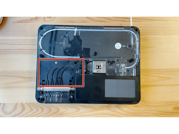
Gently lift and remove the substructure from the bottom casing.
-
You'll now be able to replace the main board, fans, and other components.
-
-
-
Remove Ingoing Driver Cover B by unscrewing the two thumbscrews, and lifting the acrylic cover.
-
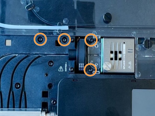
Using the torx screwdriver, remove the two screws holding the cutter wheel assembly and the two screws holding cutter motor.
-
-
-
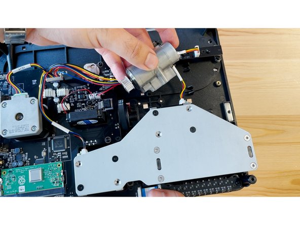
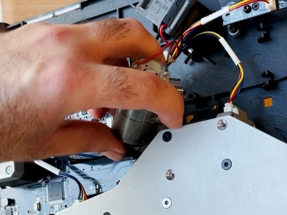
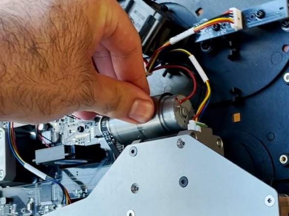
Flip the substructure over, and remove the cutter motor from its position. Keep the motor wiring plugged in.
-
Set the motor aside, and hold the motor in place while flipping the substructure over again to return to the front of the unit.
-
-
-
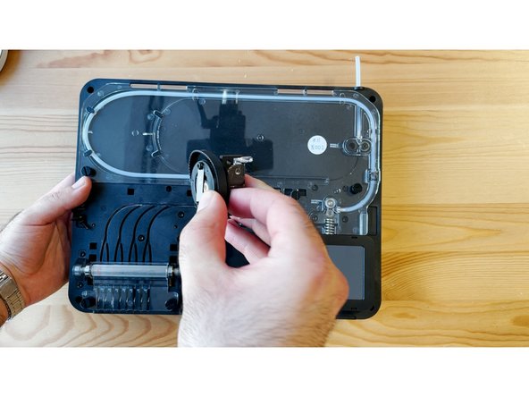
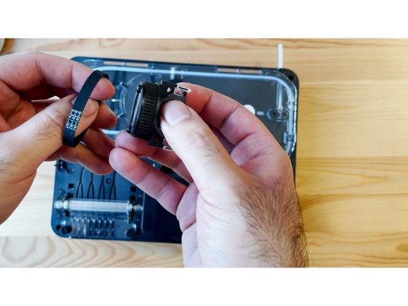
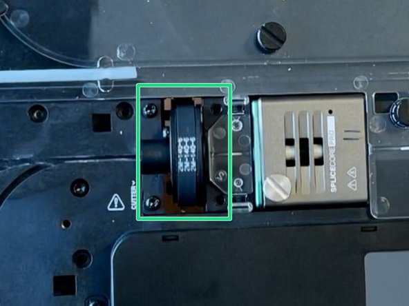
Lift the old cutter wheel assembly from the substructure. Set the cutter belt aside.
-
Place the old cutter belt onto the new cutter wheel assembly, before returning back into the unit.
-
-
-
Hold the cutter wheel assembly while flipping the unit to face the bottom of the substructure.
-
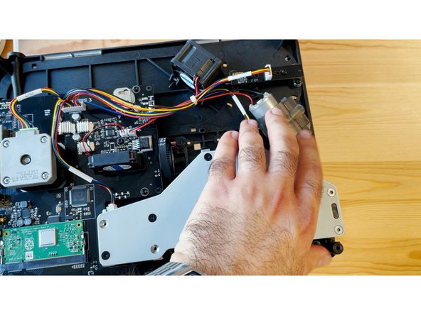
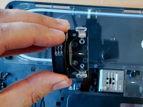
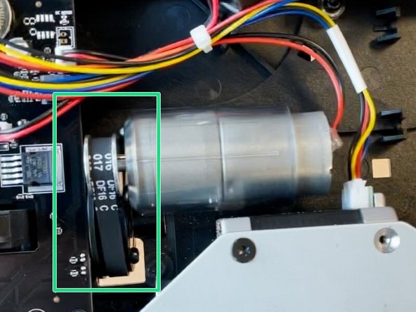
Insert the gear end of the motor into the belt, and then re-align the pins on the motor to its original position on the substructure.
-
-
-
Check that the belt is around the cutter wheel sprocket.
-
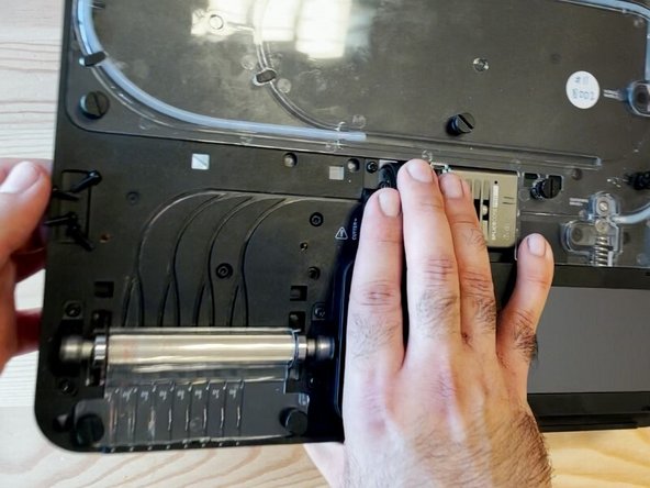
Holding the motor in place with your hand, replace the two screws to hold the motor in place. Proceed with the other two screws to hold the cutter wheel assembly.
-
For the two screws holding the cutter wheel assembly, avoid over-tightening to prevent threads from stripping.
-
Check that the cutter wheel assembly and motor are back in place, and that the belt is both on the cutter wheel sprocket, and motor.
-
-
-
Place the ingoing drive cover back in place and secure with the two thumbscrews.
-
Place the substructure back into the bottom casing, and secure back into place with the four screws.
-
Snap the IO plate cover back into place.
-


If you have any additional questions, please send us a message at support@mosaicmfg.com
If you have any additional questions, please send us a message at support@mosaicmfg.com
Cancel: I did not complete this guide.
One other person completed this guide.
