
Introduction
This guide shows how to replace the Printed Circuit Board (PCB) in the Fixed End.
-
-
Power off Element and remove the power plug
-
For ELA units, remove the bolts on the top panel and remove the panel. For desktop Element units, remove the top lid
-
Remove the Print Head from the Fixed End, following Step 2 in this guide
-
-
-
Move the Fixed End to a location on the printer where you will be able to access the screws on the rear side of the Fixed End Assembly
-
Remove the two M3x5mm button head screws
-
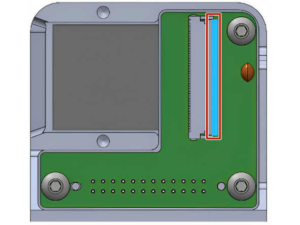
Remove the clamp above the FFC (flexible flat cable)
-
-
-
Flip the black plastic clip on the Fixed End PCB to the open position
-
Gently pull the FFC out of the connector. Be very careful not to bend the pins (if there is resistance during this step, ensure the clip is fully disengaged)
-
-
-
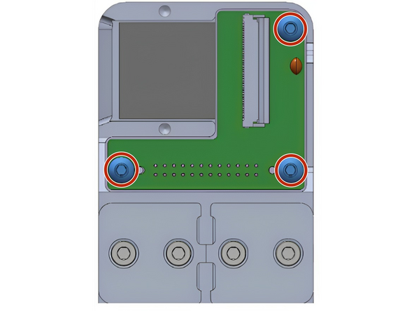
Remove the three M3x5mm button head screws
-
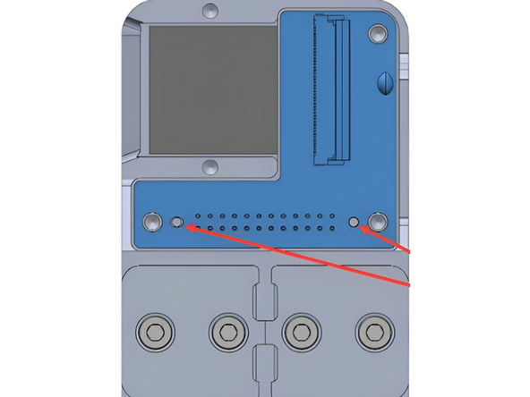
Remove the Fixed End PCB from the Fixed End Mount. There are two locating pins near the bottom of the board, be careful with these when removing the board
-
-
-
Screw the replacement PCB into place, and complete the above steps in reverse order
-
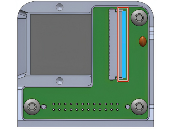
NOTE: When installing the FFC into the PCB, ensure that the black plastic clip is open, so that the FFC can slide in without resistance. Do not use force to overcome any resistance.
-
Ensure that the FFC is fully pressed in, and perpendicular to the clip, so that the electrical connections line up. You can then latch the black plastic clip down
-
Reinstall the FFC clamp and Print Head. For ELA units, reinstall the top panel
-


Contact Mosaic support at support@mosaicmfg.com
Contact Mosaic support at support@mosaicmfg.com
Cancel: I did not complete this guide.
One other person completed this guide.

Team
