Introduction
In the event that the bearings or brackets on the ingoing drive have visible damage or wear, these parts can be replaced. Please contact support@mosaicmfg.com with photos of the ingoing drive for replacement parts.
In this guide you will learn:
- How to disassemble the ingoing drive.
- How to replace the ingoing drive brackets and the bearings inside it.
Tools
Parts
No parts specified.
-
-
Remove Palette's top lid.
-
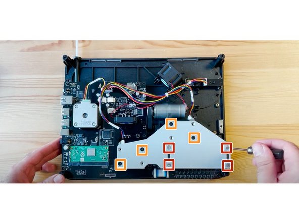
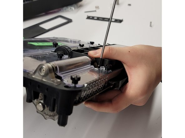
Using the provided Torx screwdriver, remove the 4 screws on each corner of the substructure.
-
-
-
Remove the IO plate cover from the unit, by pulling the tab on the Ethernet port. The IO plate cover is snap-fit to the unit and can be placed back easily.
-
Gently lift and remove the substructure from the bottom casing.
-
You'll now be able to replace the main board, fans, and other components.
-
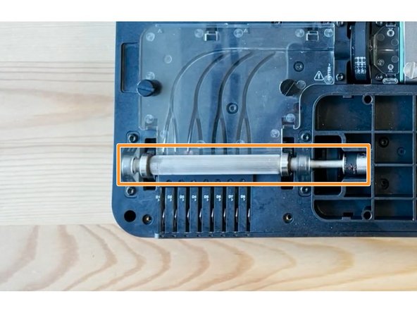
-
-
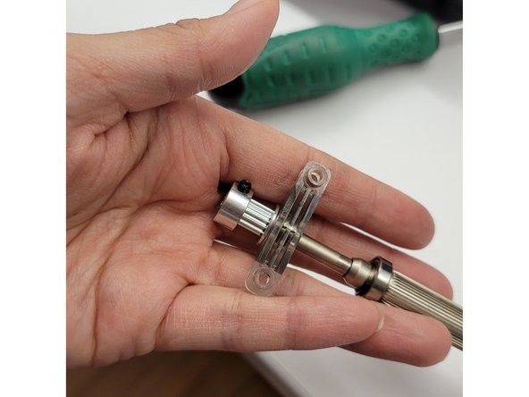
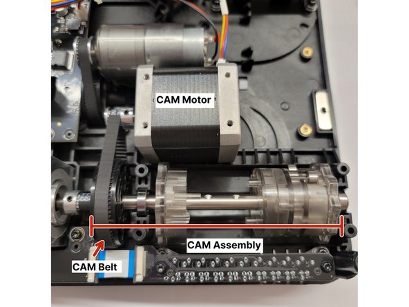
Ingoing drive brackets, with the bearing installed in the middle of the bracket.
-
Ingoing drive gear shaft
-
Ingoing drive belt, and sprocket with set screws
-
-
-
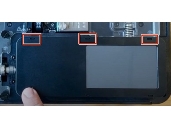
Remove the screen cover by lifting it using these tabs.
-
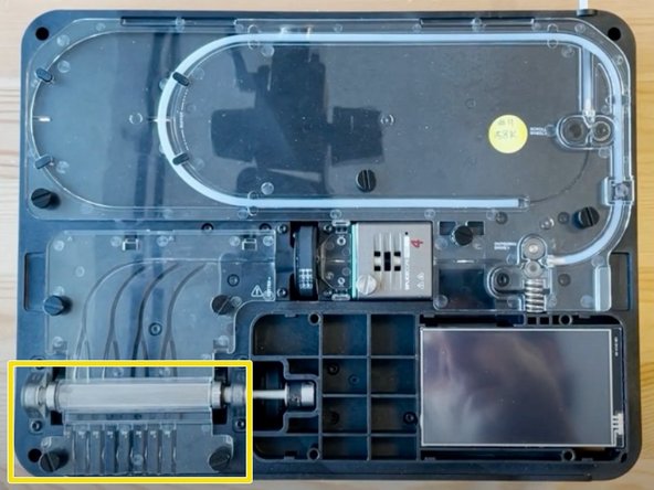
Remove acrylic ingoing drive cover A.
-
-
-
Flip substructure so that the screen is on the bottom, and the electronics are facing up. Using the torx screwdriver provided, undo CAM bracket screws.
-
Black screws will release the bracket.
-
Silver screws will release the CAM from the bracket.
-
-
-
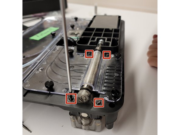
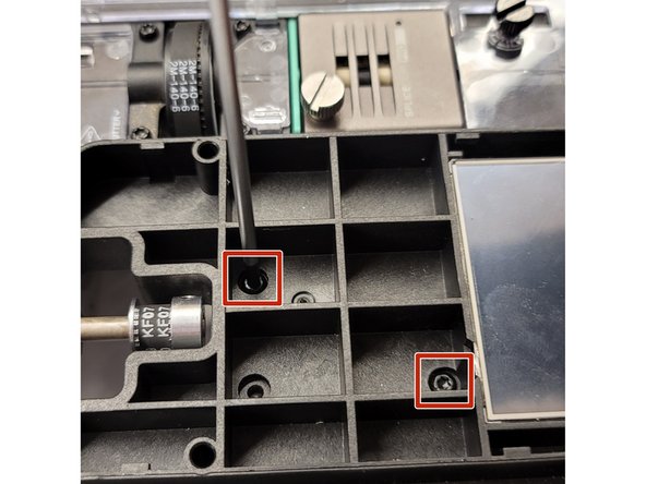
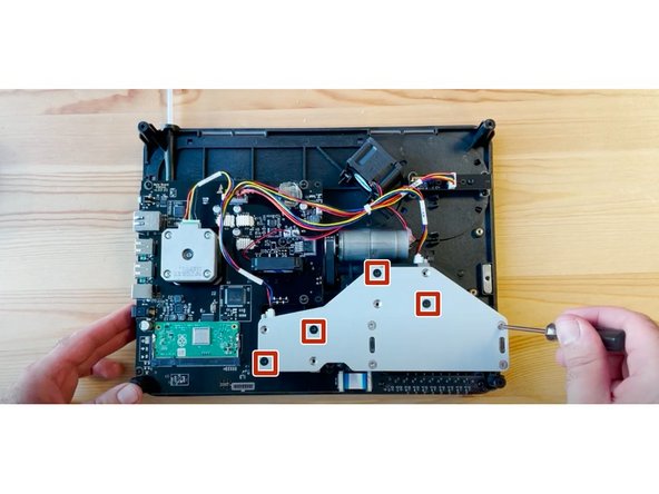
Flip the unit back over to view the top of the unit. Use the Torx screwdriver provided, undo 4x screws on both of the ingoing drive bracket
-
As these screws are loosened, they will release the CAM and endcaps underneath that were held by the CAM bracket. Please also be careful removing the CAM endcaps as there is a spring on each side.
-
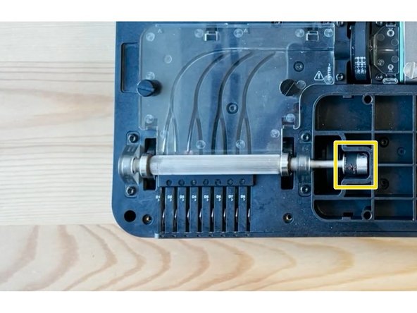
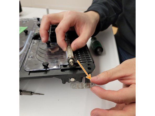
Once the screws for the ingoing drive brackets are removed the drive gear shaft can be moved freely. Release the drive gear shaft from the ingoing drive belt on the right side.
-
Remove the ingoing drive bracket from the far left end of the drive gear shaft, closest to drive 1.
-
-
-
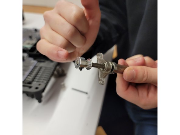
To remove the ingoing drive bracket on the other side, use a 1.5mm Allen key to loosen set screws in order to remove sprocket from the right side of the drive gear shaft, near the screen and closest to drive 8.
-
The set screws do not have to removed completely, but if they happen to fall out they can be set aside and put back in place later during reassembly.
-
Pull off sprocket along with the ingoing drive bracket, using pliers if necessary.
-
-
-
On the ingoing drive brackets, remove the old bearing by using the bottom of a screwdriver to push it out.
-
Insert the new bearing into the ingoing drive bracket, again using the bottom of a screwdriver to push it towards the middle.
-
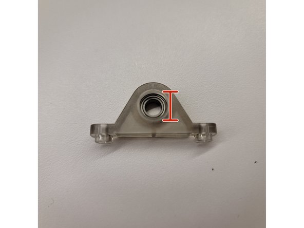
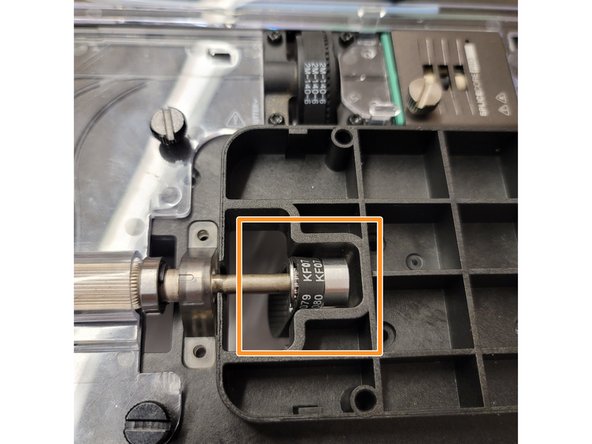
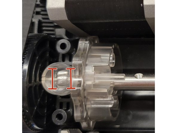
There should be equal spacing between the bearing positioned in the middle, and the edge of its slot.
-
View of how the bearing should be positioned in the very middle of the ingoing drive bracket.
-
-
-
On the right side of the drive gear shaft which is placed near the screen, slide back on the new ingoing drive bracket first, and then the sprocket. Tighten the small set screws back into place.
-
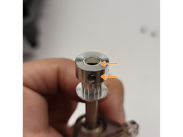
There is a small notch on top of the ingoing drive bracket, which should be facing towards the middle of the drive gear shaft. Similarly, the left ingoing drive bracket's notch should also face towards the middle of the drive gear shaft.
-
One of the set screws should be positioned on the flat end of the drive gear shaft.
-
-
-
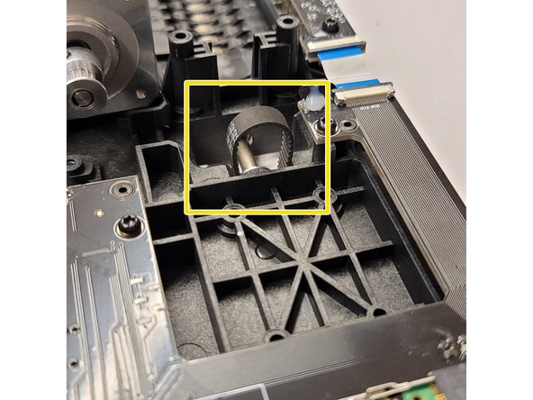
Release motor by loosening these screws to the right of the ingoing drive gear shaft, inside the screen bezel
-
Put the drive gear shaft back in place with the belt around the sprocket.
-
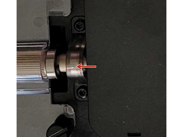
View of the belt from the bottom side of the unit, where the motor is.
-
-
-
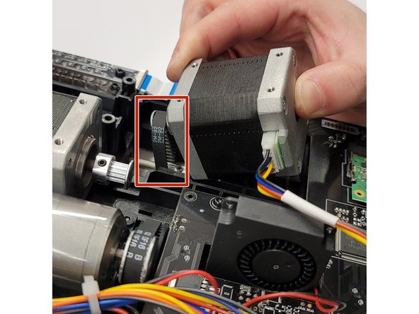
Flip the unit upside down, place motor sprocket back around the belt.
-
Holding the motor in place with your hands, flip the unit back so that the electronics are now at the bottom and screen is on top. Place screws back into the substructure for the motor, half tight at first. Once the motor is back in its position, finish tightening the screws.
-
-
-
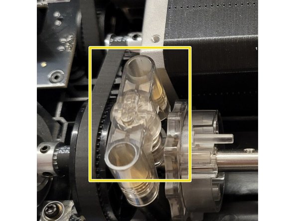
Before reassembling the end caps for the CAM, place the CAM back in its position like the photo shown. The black CAM disc and CAM belt will be pointed towards the left.
-
-
-
Flip the unit over again to begin reassembling the CAM caps. Start with one end at a time, starting from the end with the sprocket.
-
The follower cap has two notches on its bottom side, these notches sit on top of the bearing.
-
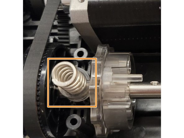
Next, place the spring in the middle.
-
Place spring cap on top.
-
-
-
Support the re-assembled CAM caps with your hand to hold it in place, insert the long screws from above and tighten to secure. For the first CAM cap assembly, tighten enough to hold the end piece in place.
-
Repeat step 13 for the last CAM cap assembly. Once each assembly is held by the screw, continue to tighten the long screws.
-
-
-
Flip the unit back to face the bottom. Reassemble bracket, putting black screws back on diagonals half tightened.
-
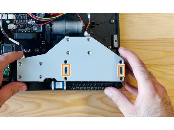
Once the screws are half tightened, you should see a small acrylic end from the two CAM caps, and two holes on the bracket. Gently position and push the bracket over these acrylic ends, before re-inserting the remaining silver screws to hold them in place.
-
Proceed with returning the substructure to the bottom casing by replacing the four screws on each corner, and then place back the IO board and screen covers.
-
After re-assembly is complete and all covers are back in place, test the ingoing drive and CAM in x-ray mode. The Controls menu can also be used to test each input.
-