
Introduction
The ingoing drive board on Palette 3 (Pro) is used for the filament inputs. If you find that a filament input is not responding to filament contact, this board may require replacement. Use x-ray mode to test each of the filament inputs and take note of any inputs that do not change its status.
Tools
Parts
No parts specified.
-
-
Remove Palette's top lid.
-
Using the provided Torx screwdriver, remove the 4 screws on each corner of the substructure.
-
-
-
Remove the IO plate cover from the unit, by pulling the tab on the Ethernet port. The IO plate cover is snap-fit to the unit and can be placed back easily.
-
Gently lift and remove the substructure from the bottom casing.
-
You'll now be able to replace the main board, fans, and other components.
-
-
-
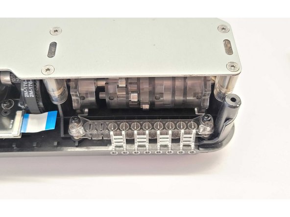
Use the provided Torx screwdriver to remove the two screws holding the board in place.
-
-
-
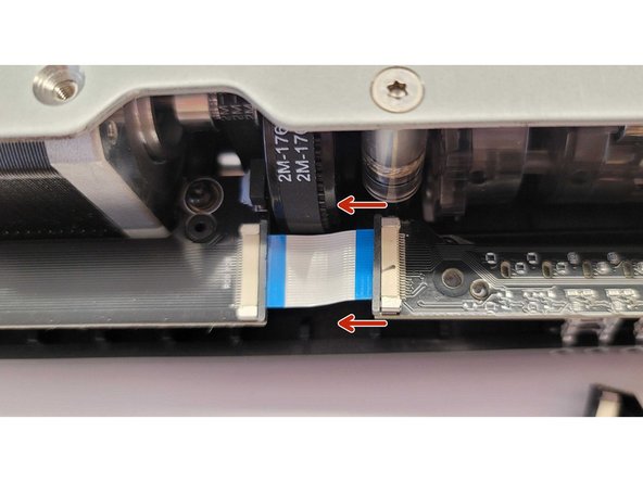
Gently push the black tab on the connector towards the left to release the ribbon cable.
-
Remove the old ingoing drive PCBA.
-
-
-
Place the new ingoing drive PCBA into place, with the cable connector towards the left. Align the holes for the screws so they can be re-inserted into place.
-
Insert the ribbon cable back into the new ingoing drive PCBA. Once the cable is inserted, push the black tab towards the right to secure in place.
-
-
-
Place the substructure back into place, and screw the mounting screws back.
-
Power on the unit, and use x-ray mode to test each input. Each input should change its status when filament makes contact with the metal switches.
-


If you have any questions, please don't hesitate to contact us at support@mosaicmfg.com.
If you have any questions, please don't hesitate to contact us at support@mosaicmfg.com.
