Introduction
In this guide you will learn how to:
- Replace the CAM belt in your Palette 3/Palette 3 Pro
Tools
Parts
Video Overview
-
-
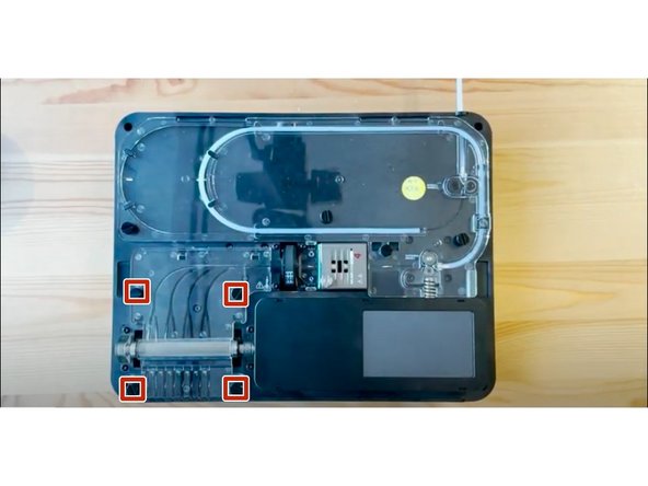
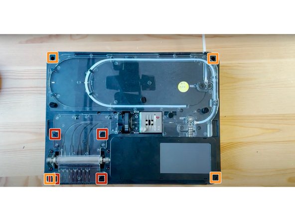
Undo the 4 screws in each corner in order to remove the bottom casing.
-
Also, remove the IO plate cover by pulling from the middle to release it from the Ethernet port.
-
-
-
Lift substructure to release it from the bottom casing.
-
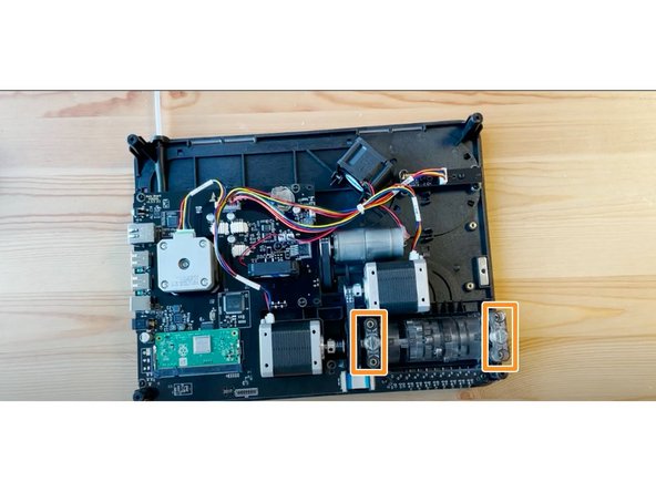
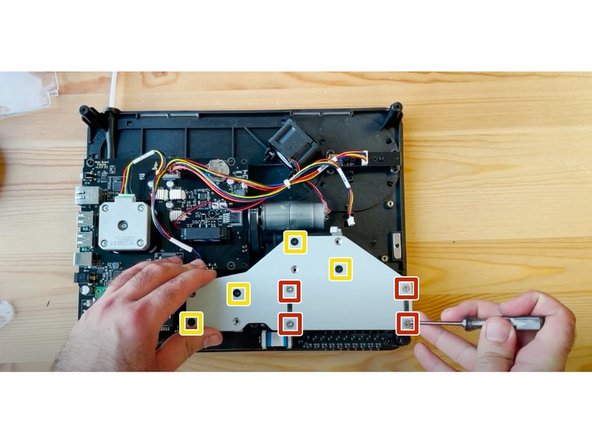
Remove CAM support bracket by:
-
Removing the 4 silver nuts
-
Removing the 4 counter-sunk screws
-
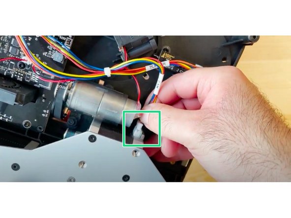
Disconnect the cable connecting the CAM motor.
-
-
-
Remove outgoing cover by undoing the thumbscrews holding it in place.
-
Then remove the 4 screws holding the CAM in place.
-
Hold the substructure in place by holding it against a flat surface, to secure the CAM spring while removing these 4 screws.
-
Hold the CAM from underneath while flipping your Palette over to the other side.
-
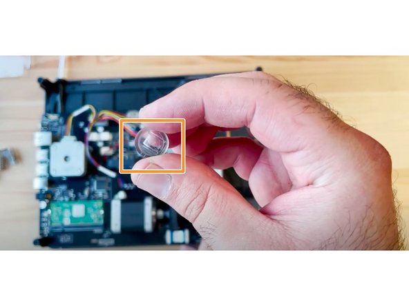
Remove the two CAM spring supports on each side.
-
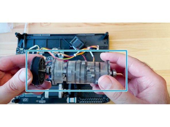
Remove the CAM assembly.
-
-
-
Remove old CAM belt, and place the new belt around the motor and CAM black disk.
-
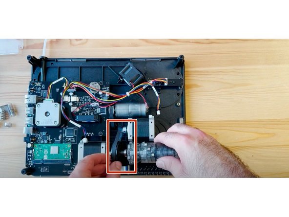
Place CAM back into place.
-
-
-
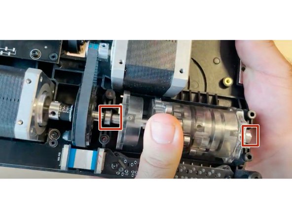
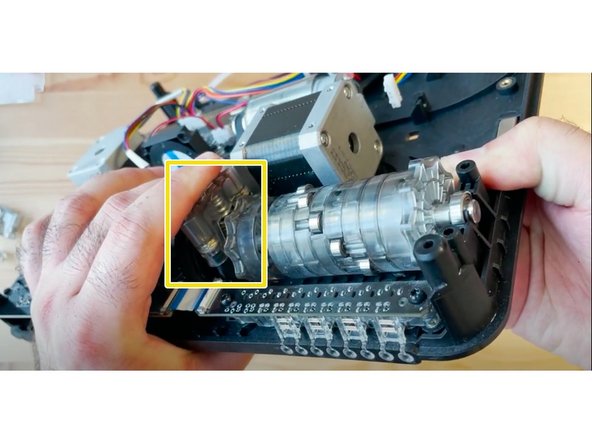
Support the ingoing gear from underneath.
-
Check that the CAM's bearings are resting in place.
-
Put the CAM follower piece back into place, such that the small indentations align horizontally with the CAM.
-
Place the spring back on top of the follower piece.
-
Place the CAM's spring end cap on top of the spring. Follow the end piece while holding the ingoing drive from underneath with your other hand to compress the spring.
-
-
-
Flip the unit over while supporting both the CAM and ingoing drive, and replace 2 of the front screws to secure the end cap.
-
While tightening the screws, apply some force to the CAM end cap on the other other side to compress the springs.
-
Do not tighten these screws all the way, so you can install the other CAM end cap.
-
Repeat steps 5 and 6 for the end cap on the other side of the CAM motor. Fully tighten the right side screws.
-
-
-
Before reinstalling the other covers, ensure that:
-
All screws are properly tightened.
-
The end cap as well as the CAM motor are properly in place.
-
Check that the follower piece indentations are horizontal.
-
Check that the CAM belt is both on the motor and the CAM sproket.
-
-
-
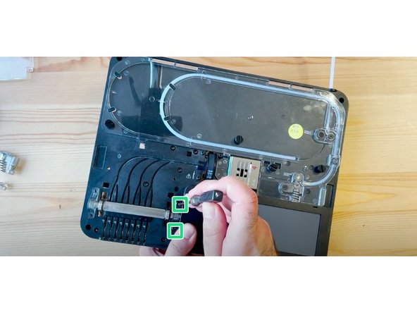
Place the CAM support bracket back, aligning with the tabs on the endcaps.
-
Return the 8 screws:
-
Place the 4 silver nuts.
-
The 4 black counter-sunk screws are placed diagonally on the motors.
-
Half-tighten the screws initially to ensure that the plate is aligned. Once you have ensured it is placed correctly, fully tighten the screws.
-
Reconnect the CAM motor cable.
-
-
-
Replace the ingoing drive covers, by placing them and tightening the thumbscrews.
-
Place the bottom casing back by seating the unit back into it.
-
Return the 4 screws in the outer corners.
-
Snap the IO plate back into place by aligning it, and ensure it snaps into place.
-
If you have any additional questions, please send us a message at support@mosaicmfg.com!
If you have any additional questions, please send us a message at support@mosaicmfg.com!
Cancel: I did not complete this guide.
One other person completed this guide.


