
Introduction
In rare instances, Palette 2's main board can short or become damaged and a replacement is necessary. In these cases, please contact our Support Team (support@mosaicmfg.com) to diagnose these issues so that the required parts are provided to you.
Tools
Parts
Video Overview
-
-
Turn Palette 2 off and remove the top lid by gently lifting from the sides.
-
Remove the acrylic ingoing cover by loosening the five thumbscrews counterclockwise.
-
Remove the 4 screws holding the bottom casing to the substructure. Two are located at the top two corners of Palette 2 while the other two are under the ingoing cover.
-
Once the screws are removed, grip Palette 2 together by the substructure and bottom casing together and flip so that the screen is facing down.
-
Please remove the SD card before completing this step as damage may be caused to your unit if left in. The substructure is connected to the bottom casing by a bundle of wires. Slowly and carefully lift the casing from the bottom up while ensuring that the wire bundle is not pulled abruptly.
-
To fully detach the bottom casing, unplug from the electronics tray, leaving only the substructure.
-
-
-
The main board is located at the top left corner of the substructure. Unplug the the three remaining wires on the board. It's fine if you forget the order of the plugs, as each plug is unique and will only attach to the board in one orientation.
-
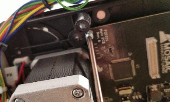
Remove the 5 screws holding the main board.
-
Gently lift main board to reveal a ribbon cable attached to the Screen PCB.
-
Using your finger or supplied screwdriver, gently push the two small tabs on the side of the cable clip to release the cable.
-
-
-
Place the blue and white ribbon cable back in place (gently insert until it's level and can no longer go further) and push down the sides of the clip to hold in place. Re-tighten the screws on the main board.
-
Re-plug the connections to the main board and ensure that the pins are pressed firmly into the inputs. Re-assemble the unit.
-


If you have any additional questions, please send us a message at support@mosaicmfg.com.
If you have any additional questions, please send us a message at support@mosaicmfg.com.
