
Introduction
There may be instances where the I/O board inside Palette becomes detached or damaged. This board has the different ports and power supply tether. You can determine if the I/O board inside Palette 2 would require replacement by checking these steps.
Tools
Parts
-
-
Plug in Palette 2 to your computer by USB and the power supply, and follow the instructions for updating firmware.
-
Launch the firmware update to Install Latest. If you receive the error No Ports to Check when attempting the firmware update (with power and USB plugged in), it's possible that a chip on the I/O board has damaged and would require replacement.
-
Please email support@mosaicmfg.com if you need assistance with determining if you require a replacement.
-
-
-
Turn Palette 2 off and remove the top lid by gently lifting from the sides.
-
Remove the acrylic ingoing cover by loosening the five thumbscrews counterclockwise.
-
Remove the 4 screws holding the bottom casing to the substructure. Two are located at the top two corners of Palette 2 while the other two are under the ingoing cover.
-
Once the screws are removed, grip Palette 2 together by the substructure and bottom casing together and flip so that the screen is facing down.
-
Please remove the SD card before completing this step as damage may be caused to your unit if left in. The substructure is connected to the bottom casing by a bundle of wires. Slowly and carefully lift the casing from the bottom up while ensuring that the wire bundle is not pulled abruptly.
-
To fully detach the bottom casing, unplug from the electronics tray, leaving only the substructure.
-
-
-
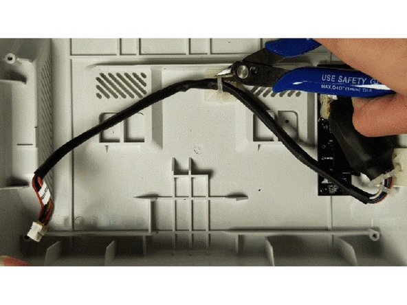
Snip the two zip-ties holding the tether to the bottom casing.
-
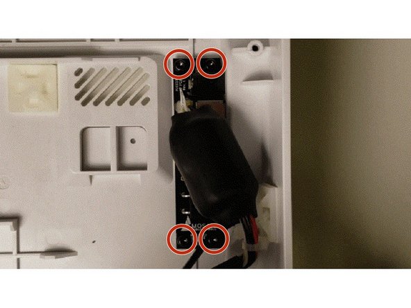
Unscrew the four bolts from the I/O board.
-
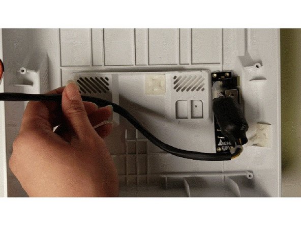
Carefully lift the existing I/O board out.
-
-
-
Re-position the new I/O board to fit the inputs on the side.
-
Re-screw the four bolts.
-
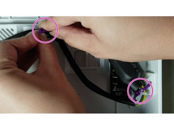
Insert the zip ties through the plastic squares on the bottom casing to secure it. Re-attach the tether with the zip tie and clip the zip tie of extra length. Try to leave some room with the zip tie loop to make it easier to detach in case needed in the future.
-
Plugin in the tether from the I/O board back into the main board, replace the bottom casing onto the substructure, and re-assemble.
-


If you have any additional questions, please send us a message at support@mosaicmfg.com.
If you have any additional questions, please send us a message at support@mosaicmfg.com.
Cancel: I did not complete this guide.
One other person completed this guide.
