
Introduction
There are rare instances when your electronics tray may have been damaged and needs to be replaced. To check if you need a replacement electronics tray, please send a message to our Support Team to diagnose the issue. If it is determined that your Palette™/P+™ electronics tray needs to be replaced, please follow our video and instructions below.
Video Overview
-
-
We suggest taking a picture of your electronics board and wiring prior to beginning the electronics tray replacement. Over Palette's production life there have been minor changes to the coloring of certain wires, so the instructions below may need to be slightly adjusted to account for these differences.
-
The connections, from left to right, would be hall PCB, splicer PCB, cutter PCB (1)
-
More recent versions of Palette+ now only have 1 thermistor, and it would be connected to T0. (2)
-
The Opto PCB is placed in the highlighted section (3)
-
-
-
The connections in (1) are arranged in this manner. Please note the orientations of the wires.
-
D1-D3 on the diagram above are connected in the second picture.
-
On the Opto, the wiring should be Signal, Ground, Voltage, while the plug is reversed on the board. On the Opto PCB, if you have colored connectors, in this image from left to right it will be red, black, green.
-
-
-
If you have the colored connectors, on the RAMPS board the connection from left to right will be green, black, red, while the orientation of the white wires would also be reversed.
-
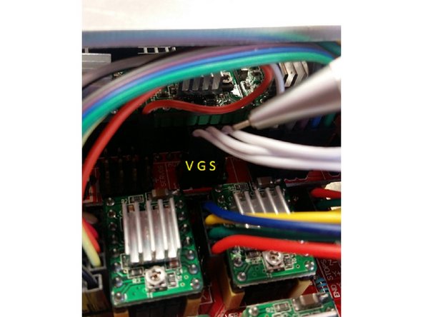
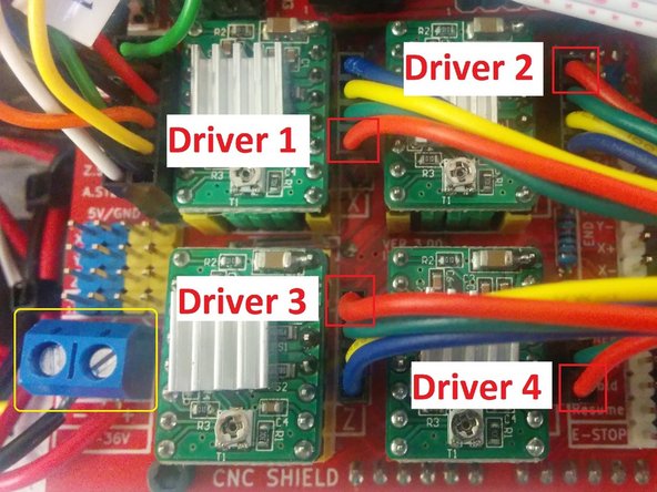
Please refer to the diagram of our stepper motors and note the orientation of the red wires for each input motor.
-
In addition to the driver connections, the blue terminal on the CNC shield is for the power socket. The black wire should be on the left and red should be on the right.
-
Once the tray has been replaced, please turn on Palette+ and run Splicer Distance and Steps Per Count. These can both be found under Calibration on Palette+'s screen.
-


If you have any additional questions, please send us a message at support@mosaicmfg.com
If you have any additional questions, please send us a message at support@mosaicmfg.com
