
-
-
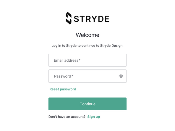
Open your web browser and navigate to the Stryde Design web portal.
-
Enter your login email address and clinic password to access your design workspace.
-
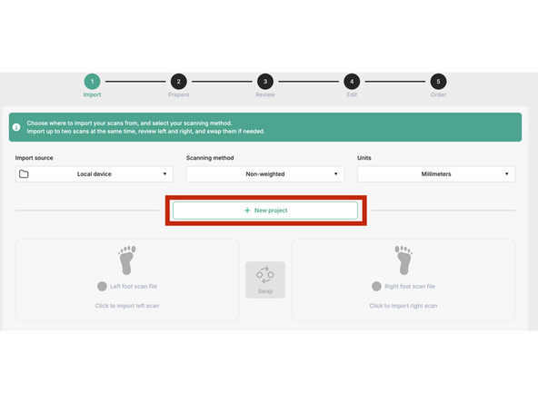
Click 'New Project' to start a new pair of custom orthotics.
-
-
-
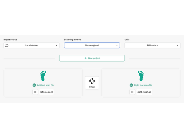
Select your file source and upload your patient's 3D foot scan (.stl or .obj format).
-
Select the scanning method used:
-
Non-weighted: a scan obtained from a foot held in the air
-
Foambox: a scan obtained from a foam impression box
-
Semi-weighted: a scan obtained from a foot applying a partial, controlled amount of weight
-
Weighted: a scan obtained from a standing foot with full weight applied
-
Ensure the units of measurement (millimeters) match the original scan file for 100% accurate sizing.
-
Files labeled 'Left' and 'Right' are automatically mapped to the correct foot.
-
-
-
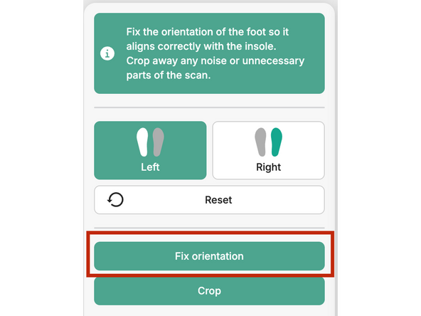
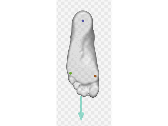
Select either foot and click 'Fix Orientation'. Rotate the foot so you are looking at the sole - right-click in the space next to the foot, hold right-click, and rotate.
-
Place Landmark 1 (MPJ1) at the base of the big toe (ball of the foot).
-
Place Landmark 2 (MPJ5) at the base of the little toe on the outer edge of the foot.
-
Place Landmark 3 (Center of Heel) right in the dead center of the heel cup.
-
Ensure the foot toes point directly along the big green direction arrow. This should automatically orient after applying the landmarks.
-
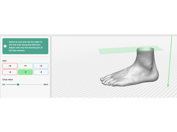
Use the 'Crop value' slider to trim away any unwanted scan borders, such as foam impression box edges.
-
Repeat for the other foot.
-
-
-
Review the bottom scan view, then click Next to enter the Edit Shell stage.
-
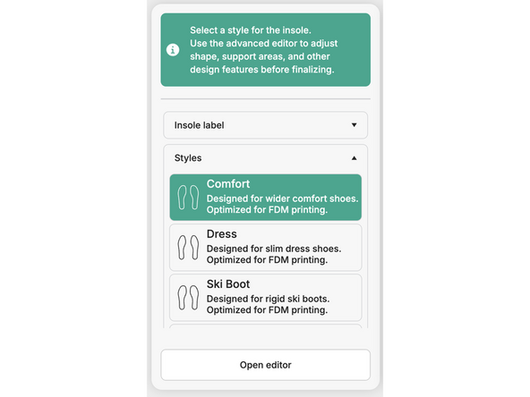
Select your desired insole style (such as Comfort, Sneaker, Sport, or Dress). Full length styles should be used with Aero, and three-quarter length styles used with Align.
-
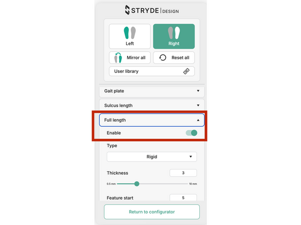
Click 'Open editor' to open the full project settings. Navigate to the 'Full Length' tab and check this is toggled to 'Enable' for an Aero print. For an Align print, this will be disabled.
-
Enabling Full Length creates a smooth, flat bottom surface that is perfectly optimized for belt 3D printing.
-
Adjust shoe size, arch height, and heel cup depth using the intuitive sliders, or add metatarsal pads as clinically needed.
-
We recommend keeping 3mm as a minimum thickness for the insole. You can customise this in the 'Full length' tab as well.
-
-
-
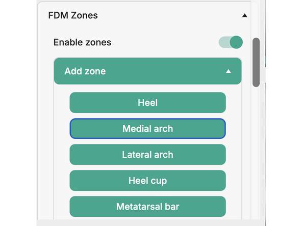
'FDM zones' refer to defined regions of varying density and stiffness across the orthotic. The specified regions will print using a different shore hardness.
-
If you wish to enable one or more FDM zones, toggle 'Enable zones' under the 'FDM zones' tab, and select which zone(s) you wish to use. In this example, a medial arch is selected.
-
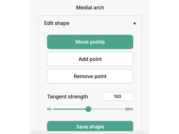
After selecting and enabling a specific zone, scroll down to edit the shape of the zone as desired.
-
Proceed to Step 6 - you will specify the desired shore hardness of your zone(s) when submitting the order.
-
For more information in designing FDM zones, refer to our Shore Hardness Mapping guide
-
-
-
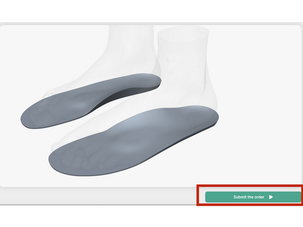
Review both left and right insoles in the 3D preview window. Once done, click 'Return to configurator'.
-
Once ready, click 'Submit the order' in the bottom right. This will allow you to submit your order to Stryde Print and add it to the queue.
-
Alternatively, you can export the print files and run them from USB, if preferred.
-
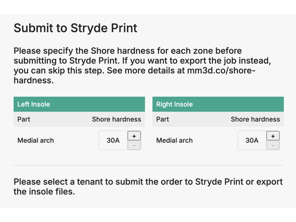
If you are using FDM zones, you will be prompted to select the desired shore hardness for your zones. After adjusting, send the order to Stryde Print, or export print files.
-
Cancel: I did not complete this guide.
One other person completed this guide.
